I/O Board
Once we had built the CPU and memory board we prototyped an LCD display for output from the Alice 2. Later we added an interface to a standard PC keyboard using an EPROM and microcontroller. The microcontroller brought serial I/O for free. Thus our I/O board gave Alice 2 user input and output and a way for us to control Alice 2 from another computer.
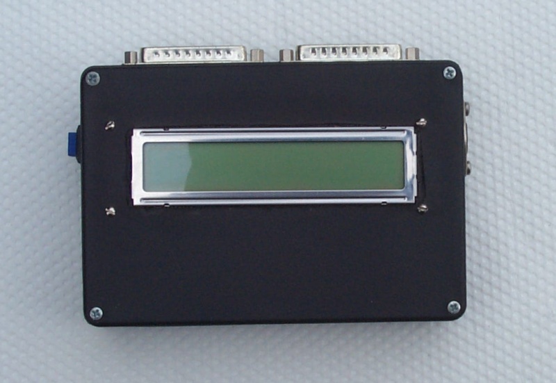
Before we had the I/O board, we built a simple LCD controller that plugged right into the alice bus. I mean, it was fun single stepping the CPU and watching the address and data accesses on the debug board, but that got boring real quick. At first we used a backlit 1 line by 8 character LCD that Brad found cheap at Halted Electronic Supply, but later we ordered a 2 line by 16 character LCD (no backlight) from JDR Microdevices so that we'd have more room. Brad thinks that the backlight was more important in the end than more room just because the garage was usually pretty dark. The box in this photograph contained the LCD and the interface logic. You can see two DB-25 connectors sticking out the top from which we ran cables to the Alice 2 bus. Both LCDs we used were typical of a lot of contemporary LCD designs; the host circuit sends data bytes to store ASCII characters on the display and instruction bytes to clear the display, set the cursor position, initialize the controller, etc. The interface board we built had a simple decoder circuit to turn I/O writes to address 2 and 3 into data and instruction writes. You can read our Z-80 ROM library for accessing the LCD on our software page.
After we built the LCD controller, it seemed natural to design an input device. At first we thought it would have been really cool to buy one of those surplus membrane keyboards that keep popping up. But we realized that we'd have to build a complicated latching and interface circuit for such a beast. So we finally decided to build a standard AT-style keyboard interface so we could use any old AT keyboard lying around. (And, at the time, Brad had several.)
PC-AT keyboards (and PS/2 keyboards) use a pretty simple serial protocol to send keystrokes. We went to the internet (our favorite reference) and found several descriptions of the keyboard protocol. At first, we considered a simple latching circuit that would interrupt the Z-80 directly and allow it to decode the serial signal coming through.
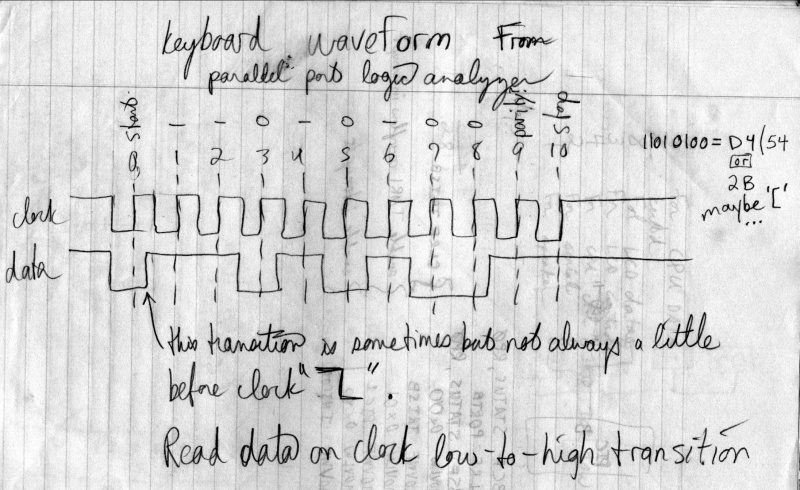
While considering that design, however, we found that JDR Microdevices was selling several variants of Microchip's PIC 16Cxx microcontrollers. We decided it would be fun to build a circuit with one of these microcontrollers that latched up the keyboard signal itself and then sent fully-formed keyboard scan code bytes to the CPU. The Z-80 would then convert these scan codes from the keyboard circuit into ASCII characters (taking into account the state of shift and control keys). This circuit slowly developed into the I/O board. The black console box shown above with the LCD also had the 5-pin keyboard connector in it, so we borrowed two bus lines to carry serial data from the console box to the I/O board. (For extra luck we also put a reset button on the console box and tied that to the bus reset line.)
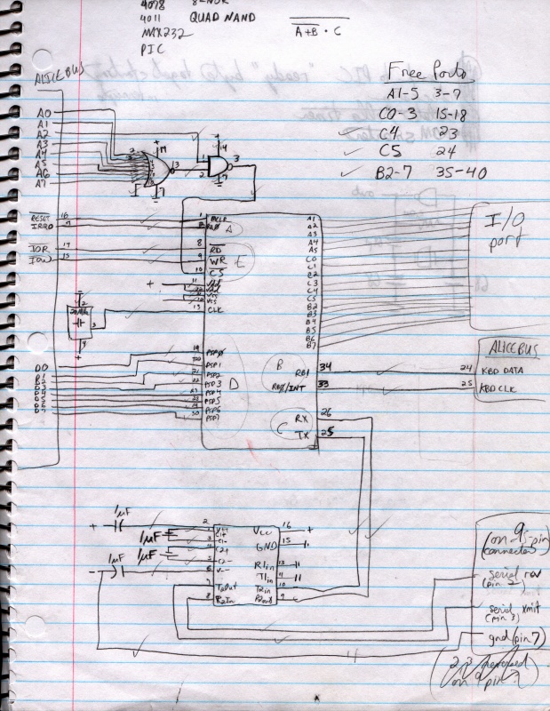
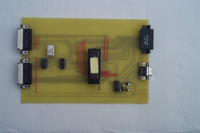
It turned out that the PIC 16C65 had a serial port built right in! So we added a MAX232 voltage converter to the board and gave ourselves an honest-to-god RS232 serial port. We later used this serial line to transfer programs and data from a PC running Linux. The 16C65 also had several I/O pins left over after our needs were met, so we decided to extend those pins to yet another DB-25 just in case we wanted to use them for something. This sketch shows the PIC microcontroller in the center connected to the Alice 2 bus on the left, the MAX232 voltage regulator at the bottom, and the spare connector to the right that exposed the unused I/O pins.